Print-to-cut only works if the file, the print, and the camera all agree on where the registration marks actually are — and the most common cause of a bad cut isn’t the machine, it’s a file or print step upstream of it that nobody checked before running the job.
Cutting a UV-printed board or shaped signage piece precisely to its printed artwork depends on the camera correctly reading marks that were placed in the file, survived the print process without distortion, and are visible enough for the camera to detect reliably. Break any link in that chain and the cut drifts off the artwork even though the machine itself is working exactly as designed.
This guide walks through the full print-to-cut workflow on the T3, from file preparation through production checks, so a shop can diagnose where a bad cut actually went wrong instead of assuming it’s a machine problem by default.
The Print-to-Cut Workflow at a Glance
Each step below depends on the one before it — a mistake early in the chain shows up as a cutting problem at the end, which is why diagnosing a bad cut means checking upstream, not just the machine.
| Step | What happens | What can go wrong |
|---|---|---|
| 1. File preparation | Cut path and registration marks placed in DXF/PLT/NC file | Marks placed too close to art, wrong size, or inconsistent placement |
| 2. Printing | Artwork and marks printed to board or media | Poor mark contrast, print distortion, media stretch |
| 3. Loading and camera read | Camera locates registration marks on the loaded sheet | Poor lighting, dirty lens, low mark contrast |
| 4. Auto-alignment | Machine calculates and applies the offset between file and actual print position | Marks outside camera’s detection range or search area |
| 5. Test cut | Verify alignment and cut quality before full production | Skipping this step on a new job or material |
| 6. Production run | Full job runs with periodic accuracy checks | Print consistency drifting partway through a long run |
File Preparation: DXF, PLT and NC Formats
In your DXF or PLT file, place registration marks consistently — same size, same relative position to the artwork, same spacing from the sheet edge — across every file in a job family, since inconsistent mark placement between files is a common, easy-to-miss cause of camera read failures that looks like a hardware problem.
DXF and PLT files typically carry the cut path and mark geometry from design software; NC files are the machine-ready toolpath output. Confirm your workflow’s conversion step between these formats preserves mark position accurately — a conversion error that shifts marks by even a small amount defeats the purpose of registration before the camera ever gets involved. Keep a template file with correctly placed marks for each standard job type rather than recreating mark placement from scratch on every new design.
Printed Mark Quality: What the Camera Actually Needs
High-contrast marks — typically solid black on a light background — printed at consistent size and without distortion are what the camera needs to read reliably; low-contrast marks, marks printed too small, or marks affected by media stretch during printing are the most common causes of unreliable camera reads.
UV printing is generally consistent, but check for banding, under-saturation, or edge softness on the registration marks specifically, not just the visible artwork — a print that looks fine to the eye can still have marks that don’t provide enough contrast for reliable camera detection. If a specific media type shows a pattern of read problems, check print settings for that media before assuming the issue is random.
How the Camera Reads and Auto-Aligns
The camera searches for registration marks within an expected area based on the file’s programmed mark position, reads their actual position on the physical sheet, and calculates the offset needed to align the cut path — this all happens automatically, but it depends on the marks being within the camera’s search range and detectable under current lighting conditions.
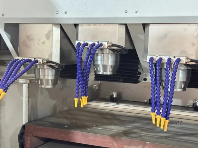
If a sheet is loaded significantly out of position, marks can fall outside the camera’s search area entirely, causing a read failure rather than a misaligned read. Confirm sheet loading procedure keeps marks within a consistent, expected zone — this is a loading discipline issue as much as a technical one.
Cutter Selection for UV-Printed Boards and Shaped Signage
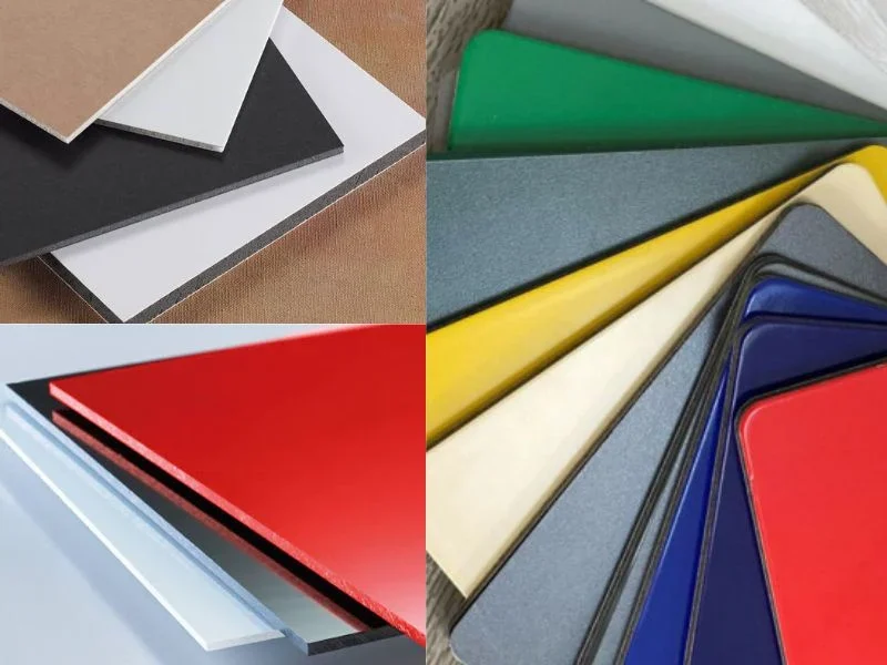
Match cutter or blade selection to the board substrate, not the printed graphic — a router bit or knife suited to the underlying board material (foam board, ACM, rigid PVC) is what determines cut quality, since the UV print layer itself is thin enough that it doesn’t significantly change cutting requirements.
For rigid board work, standard router bit selection applies based on material as usual. If your machine has the optional knife head, foam board and other soft substrates cut cleaner with the knife than with a spinning bit, which tends to compress or melt foam-core material rather than shearing it cleanly.
Running a Test Cut Before Full Production
Run a test cut on scrap or a sacrificial corner of the actual print run before committing the full job — this catches registration or cut-quality problems on one part instead of an entire batch, and it should happen on every new job, not just new material types.
Inspect the test cut for alignment to the printed artwork specifically, not just whether the cut shape is correct — a cut that’s dimensionally accurate to the file but visibly offset from the printed graphic indicates a registration issue that a shape-only check would miss entirely.
Production Checks During a Long Run
Spot-check alignment accuracy periodically through a long production run, not just at the start — print consistency can drift over a long run due to ink level changes, media roll variation, or environmental factors, and a registration setup that was accurate on part one isn’t guaranteed to stay accurate on part two hundred.
Set a check interval appropriate to your run length and material consistency history — a material with a known track record of stable printing needs less frequent checking than one that’s shown drift in the past. Catching drift early in a run limits the scrap to a handful of parts rather than discovering it at the end of a full batch.
For camera and machine maintenance specifics, see our CNC router maintenance checklist. For buying guidance, see the full T3 High-Speed Vision CNC Router specifications.
Frequently Asked Questions
Why does my cut come out fine dimensionally but offset from the printed artwork?
This points to a registration issue, not a cutting problem — check camera read accuracy and mark placement rather than the cut path itself, which is likely following the file correctly relative to wherever the camera detected the marks.
What causes the camera to fail to find registration marks?
Most commonly low mark contrast, a sheet loaded far enough out of position that marks fall outside the camera’s search area, or a dirty camera lens — check these before assuming a hardware fault.
Do I need to run a test cut on every job, or just new materials?
Every new job — registration and cut-quality issues can appear even on familiar materials if file preparation or print settings changed, so treat the test cut as a standard step, not an occasional one.
How often should I check alignment during a long production run?
Set an interval based on your material’s track record — materials with a history of stable printing need less frequent checks than ones that have shown drift before, but periodic checks on any long run catch problems before they affect the whole batch.
Should I use the router bit or the optional knife head for foam board?
The knife head, if your machine has it — foam board tends to compress or melt under a spinning router bit rather than shearing cleanly, which the knife handles better.
What file formats does the print-to-cut workflow typically use?
DXF and PLT files usually carry cut path and registration mark geometry from design software, with NC files as the final machine-ready toolpath — confirm your format conversion step preserves mark position accurately.