Feeds and speeds for aluminum fail in a way that looks backwards to most operators.
A cutter that snaps in 6061 is usually running too slow, not too fast. Back the feed off to be careful and the edge stops cutting and starts rubbing, so the heat that should have left with the chip goes into the tool instead. Aluminium then welds itself to the flutes and the tool packs solid.
This guide gives starting numbers by alloy and tool size, the geometry that matters, and a 20-minute test-cut routine for dialling them in on your own machine.
What Feeds and Speeds for Aluminum Have to Balance
Three numbers decide whether a cut works: surface speed, chip load per tooth, and whether the chips actually leave the cut. Get any one of them wrong and the other two stop mattering.
Feeds and speeds for aluminum are usually published as a single pair of numbers, which hides the fact that three variables have to agree with each other.
Surface speed controls the temperature at the cutting edge. Carbide in 6061 typically runs 500–1,000 SFM (150–300 m/min); the same tool in gummy 5052 sits at the lower end, and in cast A380 it drops again because the silicon content is abrasive. Surface speed converts to spindle RPM with a formula worth memorising: RPM = SFM × 3.82 ÷ tool diameter in inches, or RPM = m/min × 318 ÷ diameter in mm.
Chip load is the thickness of material each tooth removes per revolution, and it is the number most shops set too low. Feed rate follows from it: feed = RPM × number of flutes × chip load. A 6 mm two-flute carbide end mill at 18,000 RPM with a 0.06 mm chip load wants 2,160 mm/min. Programme it at 600 mm/min because that feels safer and the tool is now rubbing, not cutting.
Aluminium is soft enough that most operators treat chip load as a safety valve, dialling it down whenever a cut sounds rough. In this material that instinct is backwards, and the rest of this guide is about why.
Chip evacuation is the third leg, and the one that separates textbook speeds and feeds from the shop floor. Aluminium conducts heat well, so a thick chip carries most of the heat out of the cut — but only if the chip leaves. A recut chip welds to the flute, and from there the tool has minutes to live.
Why Going Slower Breaks Cutters
Below a minimum chip thickness of roughly 0.013 mm (0.0005 in), the cutting edge stops shearing material and starts ploughing through it. The edge deflects the aluminium instead of separating it, and nearly all the energy turns into heat in a tool that has no chip to carry that heat away.
What follows is predictable. The heated edge picks up aluminium as built-up edge, which changes the geometry the tool was ground with: rake angle drops, the edge goes blunt, forces climb. More force means more heat, more heat means more welding, and the flute packs solid. The tool usually breaks on the pass after the one that sounded wrong.
The diagnostic signs are consistent enough to trust. Powder-fine swarf instead of comma-shaped chips means the chip load is too low. A grey film on the flutes after a short cut is built-up edge starting. A rising note and spindle load creeping up over identical passes mean the tool is already blunted by welded material, and a finish that degrades as the job runs points the same way.
None of this is a carbide quality problem. The same tool that fails in twenty minutes at a timid feed will run a full shift at the right one, which is why tool life complaints in aluminium are usually parameter complaints.
The corrective action is the one that feels wrong: raise the feed first, not the RPM, and never lower the feed to protect a tool that is already screaming. If the machine cannot hold the higher feed rate without deflection or chatter, the answer is a smaller radial engagement so the feed can stay up, not a slower feed at full engagement.
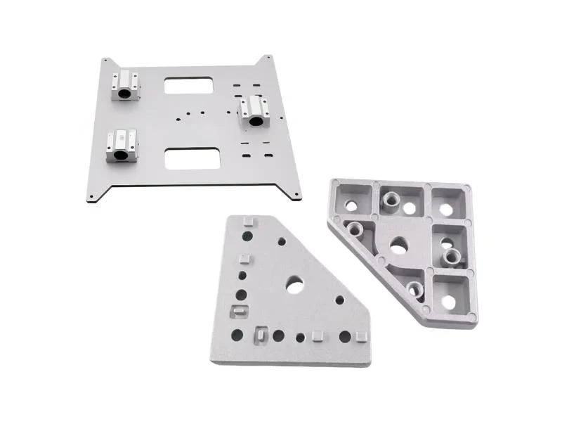
Starting Numbers by Alloy and Tool Diameter
These are starting points for solid carbide in a rigid setup, not published limits. Verify them against your tooling supplier’s data for the exact tool, then adjust with the test routine at the end of this guide.
| Tool diameter | Flutes | Chip load, 6061 / 7075 | Chip load, 5052 / soft alloys | Typical RPM at 600 SFM |
|---|---|---|---|---|
| 3 mm (1/8 in) | 2 | 0.025–0.05 mm (0.001–0.002 in) | 0.03–0.06 mm | 18,000–24,000 |
| 6 mm (1/4 in) | 2–3 | 0.05–0.10 mm (0.002–0.004 in) | 0.06–0.12 mm | 9,000–12,000 |
| 10 mm (3/8 in) | 3 | 0.08–0.13 mm (0.003–0.005 in) | 0.10–0.15 mm | 6,000–7,500 |
| 12 mm (1/2 in) | 3 | 0.10–0.15 mm (0.004–0.006 in) | 0.12–0.18 mm | 4,500–6,000 |
6061-T6 is the reference point most tooling charts are written around, and it behaves: chips break, the finish holds, and the numbers above work as printed. 7075 is harder and stronger, gives even better chip formation, and tolerates the same chip loads at slightly lower surface speed.
5052 and the softer sheet alloys are the ones that catch people out. They are gummier, they smear rather than break, and they build up on the edge faster. Counterintuitively they want a heavier chip load than 6061, along with polished flutes and a genuinely sharp edge. Running 5052 at a cautious 6061 feed is a reliable way to weld a cutter solid.
Cast alloys such as A380 carry high silicon content that is abrasive, so tool life is the constraint rather than welding. Drop surface speed by 20–30%, keep the chip load, and expect to replace tooling on a schedule rather than on failure — that is a cost-per-part line item worth tracking from the first job.
Flute Count and Geometry: Why Two or Three Beat Four
In aluminium, chip room matters more than the number of cutting edges. A four-flute end mill has half the space between teeth of a two-flute, and in a material that produces long, sticky chips, that space is what keeps the tool alive.
The geometry that works is consistent across suppliers: two or three flutes, high helix in the 35–45° range to lift chips out of the cut, polished flutes so aluminium slides rather than adheres, and a sharp positive rake. Coatings need care — a bright uncoated or ZrN-coated tool suits aluminium, whereas the TiAlN coating that performs in steel has an affinity for aluminium and encourages exactly the welding this guide is about.
Flute count also has to match what the spindle and control can physically deliver. Router spindles typically run 18,000–24,000 RPM, and at 24,000 RPM a three-flute 3 mm tool at a 0.04 mm chip load needs 2,880 mm/min.
Add a fourth flute and the machine has to hold 3,840 mm/min through corners and arcs to keep the same chip thickness. If the control decelerates into every corner, chip load collapses exactly where the tool is most loaded — which is why two-flute tools remain common on high-RPM gantry machines.
For thin sheet and profiles, single-flute tools with a large gullet earn their place. They halve the feed rate needed for a given chip load and give the chip somewhere to go, which matters more on parts where the cutter is engaged in a 2 mm wall than in a 20 mm plate.
Depth of Cut: Slotting Versus Adaptive Toolpaths
Full-width slotting is the hardest thing you can ask a cutter to do in aluminium, and it is where most broken tools happen. In a slot the tool is engaged 180°, chips have nowhere to exit, and every one of them gets a second pass through the cut.
This is where feeds and speeds stop being a table lookup and become a toolpath decision. If a slot is unavoidable, keep the axial depth to 0.5–1× tool diameter on a gantry router, cut the feed 30–50% below the table values, and clear chips aggressively between passes. Peck the slot in steps rather than committing the full depth in one pass.
Adaptive, trochoidal and other high-efficiency toolpaths exist to avoid that situation entirely. Radial engagement drops to 8–15% of tool diameter while axial depth goes up to 1–2× diameter, so the same amount of material comes off with a fraction of the engagement angle. The tool sees a shorter arc of contact, the chips have an escape route, and heat spreads along more of the cutting edge rather than concentrating at one point.
Light radial engagement brings a correction that has to be programmed, not assumed. Below roughly 50% radial engagement the actual chip is thinner than the programmed feed per tooth — the radial chip thinning effect.
At 10% radial engagement the chip is around 60% of the programmed value, so the feed needs multiplying by roughly 1.6–1.8× to keep real chip thickness in range. Skip that correction and a toolpath meant to protect the tool puts it back in the rubbing zone.
Most CAM systems apply the chip thinning factor automatically for adaptive toolpaths. Confirm it is switched on before assuming your feed is what you think it is.
Coolant, Air and Getting Chips Out of the Cut
In aluminium, evacuation is not a finishing detail; it is part of the feeds and speeds decision. A recut chip is harder than the chip that made it, welds readily, and can take a tool out in a single pass.
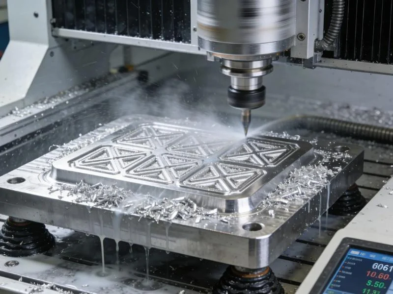
Flood coolant is the most effective option and the reason machining centres hold aggressive feeds and speeds in aluminium all day. It lubricates the edge, floats chips out of pockets and keeps the part dimensionally stable across a long cycle. On an enclosed machining centre it is straightforward; on an open gantry router it usually is not.
Coolant choice also follows the part rather than the machine. Parts that go straight to anodising or bonding cannot carry oily residue into the next process, which pushes shops towards mist or a water-soluble coolant and a proper wash step rather than heavy lubricant.
For router work, high-pressure air at 4–6 bar (60–90 psi) aimed at the cutting zone plus vacuum extraction does most of the job, and mist lubrication with a coolant formulated for aluminium handles the rest. The nozzle position matters as much as the pressure: it has to blow chips away from the next cutter path, not across the table into the vacuum zone seals.
Two points come up on nearly every install. Chips falling back into an open pocket are a recut waiting to happen, so programme the path to exit and clear. And aluminium swarf packs vacuum table channels faster than anything else this class of machine handles — a table that loses hold-down mid-cut moves the part before it breaks the tool, which makes chip extraction a work-holding concern, not housekeeping.

What a Gantry Router Holds, and Where a Machining Centre Starts
A gantry router and a machining centre both cut aluminium, but they are sized for different jobs, and pretending otherwise is how shops end up disappointed with a perfectly good machine.
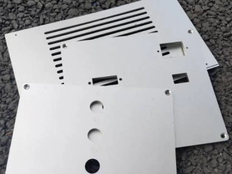
A gantry CNC router for aluminum earns its keep on large, mostly flat work: sheet and plate parts, extrusion machining, panel cutouts, sign faces, jigs and fixtures. High spindle RPM suits small-diameter tools, and the large envelope handles parts a vertical machining centre cannot fit. The trade is rigidity — light radial engagement with adaptive paths, not heavy full-width cuts.
A CNC machining centre is the answer when the work is thick, deep or tight: heavy slotting in 25 mm plate on a production schedule, deep pockets, tapped holes at depth, tolerances held across a long cycle with flood coolant. The mass and the spindle taper exist precisely to absorb the cutting forces a gantry frame will flex under.
Spindle power tells the same story from a different angle. A 9 kW high-frequency router spindle is built to remove metal fast at high RPM with light engagement, while a machining-centre spindle at similar power delivers torque low down where heavy cuts happen.
We would rather say this plainly than sell the wrong machine: if your job sheet is mostly heavy slotting and deep pocketing in thick plate, that is machining centre work, and a router will frustrate you regardless of how well its feeds and speeds are dialled in. If it is plate, sheet, extrusion and panel work at volume, the router is usually the better throughput and floor-space decision.
Most real job mixes sit between those two ends, which is why we ask for actual part drawings and the alloy before quoting either machine.
A 20-Minute Test-Cut Routine
Published feeds and speeds get you into the right neighbourhood; a test cut tells you where your machine actually sits. Budget 20 minutes on a scrap offcut of the alloy you will run, using the tool you will run.
Start mid-range from the table above: a 6 mm two-flute in 6061 at 12,000 RPM and 0.07 mm chip load gives 1,680 mm/min. Cut a 100 mm open-sided pass at 1× diameter axial depth and 20% radial engagement — open-sided, not a slot, so chips can leave.
Listen first, then look. A steady sound and comma-shaped chips that come off warm rather than hot mean the numbers are close. Then inspect the flutes under a light: bright with no deposits is correct; a dull grey smear means built-up edge is forming and the chip load needs to go up.
Raise the feed in 10% steps, running the same pass each time, until either the finish degrades, the spindle load climbs sharply, or chatter appears. Back off 10% from whatever produced the first problem, and that is your working feed. Only then adjust RPM, and only if surface finish rather than tool life is the constraint.
Record the feeds and speeds you settled on: tool, alloy, RPM, feed, axial and radial depth, coolant method, and result. A one-page table per tool and alloy pays for itself the first time an operator sets up that part on a different shift, and it turns tooling spend into a cost per part you can forecast.
On a new machine, run the routine during commissioning and fold the results into operator training. It is the fastest way to retire the “slow it down to be safe” habit before it costs a set of cutters.
Frequently Asked Questions
What is a good feed and speed for aluminum?
For solid carbide in 6061, start at 500–1,000 SFM (150–300 m/min) with a chip load of 0.05–0.10 mm (0.002–0.004 in) per tooth on a 6 mm tool, then verify with a test cut. Surface speed sets edge temperature; chip load decides whether the tool cuts or rubs.
What is the recommended feed and speed for 6061 aluminum?
A 6 mm two-flute carbide end mill at 9,000–12,000 RPM with a 0.05–0.10 mm chip load gives roughly 900–2,400 mm/min, at 1× diameter axial depth and 20% radial engagement. Treat those as starting values for a rigid setup.
What RPM should you cut aluminum?
RPM follows from surface speed and diameter: RPM = SFM × 3.82 ÷ diameter in inches. At 600 SFM that is roughly 18,000–24,000 RPM for a 3 mm tool and 4,500–6,000 RPM for a 12 mm tool. High RPM alone protects nothing — feed has to rise with it.
What are the common milling feeds and speeds for aluminum?
Most shops work from a chip load table by tool diameter, apply radial chip thinning for adaptive paths, and cut feed 30–50% when slotting. The table above covers 3–12 mm tools in 6061, 7075 and softer 5052-type alloys.
Why do my end mills break when I slow the feed down?
Below about 0.013 mm chip thickness the edge ploughs instead of cutting, heat stays in the tool, and aluminium welds to the flutes as built-up edge. Forces climb until the packed tool snaps. The fix is a higher feed, or lighter radial engagement so a higher feed is possible.
Do I need flood coolant, or is air blast enough for aluminum?
Flood coolant is the most effective and is standard on enclosed machining centres. On an open gantry router, air at 4–6 bar plus vacuum extraction and mist lubrication handles most sheet, plate and extrusion work. Either way, chips must leave the cut.
Feeds and speeds for aluminum on a page only take you so far. Send us a drawing and the alloy, and we will run your part on the machine class you are considering — a CNC router for aluminum or a machining centre — and return the parameters we used, the cycle time and a sample part. If the honest answer is that your job belongs on the other machine, we will tell you that instead.
Contact our engineering team with your part files, annual volume and tolerance requirements, and we will come back with a cutting test rather than a brochure.