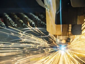
Laser cutting tolerances decide whether a laser-cut part fits first time or goes back for rework.
Most drawings call for a number the buyer has never checked against the process: ±0.05 mm on 10 mm plate, or a tight hole position on a part that will warp as it cools. The laser gets blamed, but the tolerance was never achievable for that thickness in the first place.
This guide covers the laser cutting tolerances a fiber laser can realistically hold, how ISO 9013 and ISO 2768 put numbers on it, where tolerance gets lost, and how to write a drawing a laser shop can actually meet.
What Laser Cutting Tolerances Can You Actually Hold?
On thin and mid-gauge sheet, a modern fiber laser typically holds dimensional tolerances of about ±0.05 to ±0.2 mm; published figures from laser manufacturers put the general capability under 0.25 mm (0.010 in). The number widens as the plate gets thicker, and it is always wider than the machine’s positioning accuracy.
That range of laser cutting tolerances is not a hedge. It reflects three things that change from job to job: material thickness, the size of the feature, and how much heat the part absorbs during the cut. Hypertherm, the cutting-systems maker, describes laser cut-part tolerances as under 0.25 mm and makes the point that tighter is not automatically better.
Job shops that publish their own laser cutting tolerances land in the same place. Fiber laser suppliers commonly quote ±0.05 mm at the precise end for thin sheet and small parts, and around ±0.2 mm for general work. CO₂ lasers cutting metal sit wider, and they have largely given way to fiber on sheet metal.
The practical reading for a buyer: a tolerance of ±0.1 mm on a 2 mm stainless bracket is a normal request. The same ±0.1 mm on a 20 mm plate, across a 1,000 mm dimension, is a request to machine the part afterwards — and it should be quoted that way.
What matters most is not the headline figure but which features actually need it. A part with one tight bore and twenty clearance holes should not be toleranced as if every edge were a bearing seat, because every tight tolerance on a drawing has a cost attached.
Machine Accuracy vs Part Tolerance: Three Numbers People Confuse
Positioning accuracy, repeatability and part tolerance are three different numbers, and only the last one describes the part you receive. Spec sheets quote the first two because they belong to the machine; the third depends on the material and the job.
Positioning accuracy is how closely the cutting head reaches a commanded point. Repeatability is how closely it returns to the same point again and again. Part tolerance — an engineering tolerance in the usual sense — is how far a finished dimension may vary from the drawing, and it includes everything the machine cannot control.
| MNT machine | Positioning accuracy | Repeatability | Built for |
|---|---|---|---|
| X6040 precision fiber laser (1500 W) | ±0.02 mm | ±0.005 mm | Thin-gauge sheet with fine detail |
| X5 sheet fiber laser (3 / 6 kW) | 0.05 mm | — | General sheet and plate, 3000 × 1500 mm bed |
| X6 tube laser (6 kW) | Within 0.15 mm over full length | ±0.02 mm | Round and square tube up to 6000 mm |
A machine with ±0.02 mm positioning accuracy does not produce ±0.02 mm parts. Between the command and the finished part sit kerf variation, thermal expansion as the sheet heats, residual stress released from the plate, and the flatness of the sheet on the slats.
That is why the X6040 is built on a marble frame for thin sheet rather than simply given a better controller: the mass and stiffness keep the head steady through hard acceleration, which is where small-feature accuracy is lost.
For buying purposes, use the machine figures to rule a machine out, not to promise laser cutting tolerances on your part. Ask instead for a measured sample of your own part before you send an RFQ, and compare how each machine on our sheet metal laser cutting machine page is built for the thickness you run.
What Is the ISO Standard for Laser Cutting Tolerances?
The ISO standard for laser cutting is ISO 9013:2017, which classifies the quality of thermal cuts — laser, plasma and oxyfuel — by perpendicularity of the cut face and roughness of the cut surface. Dimensional tolerances on the drawing are usually covered separately by ISO 2768-1.
ISO 9013 grades a cut into quality ranges, with range 1 the tightest, and it is the closest thing to a shared language for laser cutting tolerances on the cut face. Two measurements define each range. The perpendicularity or angularity tolerance, u, captures how far the cut face departs from square, including taper. The mean height of profile, Rz5, captures surface roughness, measured in micrometres.
Both limits grow with material thickness, which is the standard’s way of admitting what every operator knows: a thick cut is never as square or as smooth as a thin one. The formulas for ranges 1 to 4 are:
- Range 1: u ≤ 0.05 + 0.003a mm · Rz5 ≤ 10 + 0.6a µm
- Range 2: u ≤ 0.15 + 0.007a mm · Rz5 ≤ 40 + 0.8a µm
- Range 3: u ≤ 0.4 + 0.01a mm · Rz5 ≤ 70 + 1.2a µm
- Range 4: u ≤ 0.8 + 0.02a mm · Rz5 ≤ 110 + 1.8a µm
Here a is the material thickness in millimetres. Worked through for common thicknesses, the perpendicularity limits look like this:
| Thickness | Range 1 (u) | Range 2 (u) | Range 3 (u) | Range 4 (u) |
|---|---|---|---|---|
| 1 mm | 0.053 mm | 0.157 mm | 0.41 mm | 0.82 mm |
| 3 mm | 0.059 mm | 0.171 mm | 0.43 mm | 0.86 mm |
| 6 mm | 0.068 mm | 0.192 mm | 0.46 mm | 0.92 mm |
| 10 mm | 0.080 mm | 0.220 mm | 0.50 mm | 1.00 mm |
| 20 mm | 0.110 mm | 0.290 mm | 0.60 mm | 1.20 mm |
A drawing can call out the required quality with a short ISO 9013 code that combines the perpendicularity range, the Rz5 range and a dimensional tolerance class. It is far more useful to a laser shop than “clean edge”, because it can be measured.
ISO 2768 General Tolerances on a Laser-Cut Part
Most laser-cut drawings control dimensions with a general tolerance note such as “ISO 2768-m”, which sets the allowed deviation for every dimension that has no tolerance of its own. The class letter — f, m or c — decides how tight those defaults are.
ISO 2768-1 is the general-tolerance standard for linear and angular dimensions, and the usual way laser cutting tolerances are written for size. It saves a designer from tolerancing every line, and it tells the shop what “untoleranced” actually means.
| Nominal size | f (fine) | m (medium) | c (coarse) |
|---|---|---|---|
| 0.5–3 mm | ±0.05 mm | ±0.1 mm | ±0.2 mm |
| 3–6 mm | ±0.05 mm | ±0.1 mm | ±0.3 mm |
| 6–30 mm | ±0.1 mm | ±0.2 mm | ±0.5 mm |
| 30–120 mm | ±0.15 mm | ±0.3 mm | ±0.8 mm |
| 120–400 mm | ±0.2 mm | ±0.5 mm | ±1.2 mm |
| 400–1000 mm | ±0.3 mm | ±0.8 mm | ±2 mm |
| 1000–2000 mm | ±0.5 mm | ±1.2 mm | ±3 mm |
Read the table against the laser’s real capability and the laser cutting tolerances you need. The m class sits comfortably inside what a fiber laser holds on thin and mid-gauge sheet, which is why “ISO 2768-m” is the default on most sheet-metal drawings.
The f class is the one to be careful with. On small features in thin sheet it is realistic on a precision machine; on large dimensions in thick plate, heat and stress make it hard to guarantee without a finishing operation. If only a handful of dimensions need to be tight, tolerance those individually and leave the general note at m.
For thick structural plate cut at the heavy end of the fiber laser cutting thickness chart, the c class is often the honest default.
Why Thickness Changes Laser Cutting Tolerances
Thicker material widens every laser cutting tolerance: the cut tapers, the edge roughens, and more heat goes into the part. ISO 9013 builds this into its formulas, and it shows up on the shop floor as parts that measure differently at the top and bottom of the cut.
Taper is the first effect on laser cutting tolerances. The beam is focused to a point, so the kerf is not perfectly parallel through the thickness. Fabworks, a US laser job shop, puts typical taper at about 0.025 mm for every 2.54 mm of thickness — negligible on 1 mm sheet and measurable on 20 mm plate.
Heat is the second. A thick cut runs slower and puts more energy into the surrounding metal, which expands during the cut and contracts afterwards. Long, narrow parts and parts with many internal cutouts move the most.
Small features are the third. A common shop rule is that hole diameter should be at least equal to material thickness. Smaller holes can be cut, but roundness, taper and dross control get harder, and a hole that has to hold a close tolerance at that size is usually drilled or reamed afterwards.
Where Laser Cut Parts Lose Tolerance: Heat, Material and Fixturing
Most problems with laser cutting tolerances come from the material and the job layout, not from the machine. Knowing where the error comes from tells you whether to change the drawing, the material or the cutting sequence.
Residual stress in the plate. Hot-rolled plate carries stress from the mill. Cutting a part out releases it, and a long strip can bow as soon as it is free. Stress-relieved or levelled material behaves far better when flatness matters.
Sheet flatness on the slats. A sheet that does not lie flat puts the surface at different heights under the head. The height sensor follows the surface, but a wavy sheet still produces small positional errors across a large part.
Heat build-up across a nest. Cutting many parts close together in one area concentrates heat. Good nesting software spreads the cut order across the sheet so no region overheats.
Small parts tipping. A small part can tilt between slats as the last cut finishes, and the head can catch it. Micro-joints hold small parts in the skeleton until the nest is finished.
Kerf variation. The cut path is offset by half the kerf width to hit the drawn dimension, so any change in kerf moves the edge. We explain how that offset works in our guide to kerf in laser cutting.
How to Specify Laser Cutting Tolerances on a Drawing
Specify a general tolerance for the whole part, tighter tolerances only on the features that need them, and a measurable edge quality instead of words like “clean”. That combination gets you accurate quotes and fewer rejected parts.
Start with a general note — ISO 2768-m suits most sheet-metal parts. Then mark the critical features individually: a bearing bore, a locating slot, a hole pattern that has to line up with a mating part. Everything else inherits the general tolerance.
State edge quality with ISO 9013 when the cut face matters, for example on a part that will be welded or that seals against another surface. Name the datum features the part is measured from — the reference surfaces of geometric dimensioning and tolerancing — so the shop and your inspection measure the same way.
Resist tightening laser cutting tolerances “to be safe”. As Hypertherm points out, every unnecessary tight tolerance raises the price through slower cutting, extra inspection or a secondary operation. Where a feature truly needs precision beyond the laser, say so on the drawing and let it be finished by drilling or machining — it costs less than a rejected batch and a second lead time. For thin, detailed parts, our guide to choosing a precision fiber laser for thin metal covers the machine side.
Finally, send the right file format: a clean DXF, DWG or STEP at 1:1 scale, with material grade and thickness stated. If you are choosing the machine rather than the drawing, our sheet metal laser cutting machine page compares the X5, X6 and X6040 by the work each one is built for.
Frequently Asked Questions
What is the typical accuracy of laser cutting?
A fiber laser typically holds about ±0.05 to ±0.2 mm on thin and mid-gauge sheet, and laser manufacturers quote general cut-part tolerances under 0.25 mm (0.010 in). Accuracy widens with thickness, part size and heat input, and it is always wider than the machine’s own positioning accuracy.
What is the ISO standard for laser cutting tolerance?
ISO 9013:2017 is the standard for thermal cuts, including laser. It grades cut quality by perpendicularity (u) and surface roughness (Rz5), with limits that grow with thickness — for example, range 1 allows u ≤ 0.05 + 0.003a mm. General dimensions on laser-cut drawings are usually controlled separately with ISO 2768-1.
How precise can laser cutting be?
On thin sheet with a precision machine, around ±0.05 mm on small features is realistic; the MNT X6040, for example, has ±0.02 mm positioning accuracy and ±0.005 mm repeatability. Part tolerance is always looser than those machine figures, because kerf, heat and material flatness add their own error.
What are the four types of tolerances?
In geometric dimensioning and tolerancing, tolerances are commonly grouped as form, orientation, location and runout, with profile often listed separately. On a laser-cut part the ones that matter most are size, orientation of the cut face (perpendicularity, per ISO 9013) and location of holes and slots.
How do I calculate the ISO 9013 tolerance for my thickness?
Put your material thickness in millimetres into the formula for the range you need. For 10 mm plate in range 1, u = 0.05 + 0.003 × 10 = 0.08 mm and Rz5 = 10 + 0.6 × 10 = 16 µm. In range 2 the same plate allows u = 0.22 mm and Rz5 = 48 µm.
Does thicker material reduce laser cutting accuracy?
Yes. The cut tapers through the thickness, the edge gets rougher and more heat enters the part. ISO 9013 limits grow with thickness for that reason, and a hole smaller than the material thickness is hard to hold round and square without a secondary operation.
Laser cutting tolerances are easiest to agree on with a measured part in hand. Send us a drawing with material and thickness, and we will cut a free sample on the machine that fits your work so you can measure it against your own drawing. Contact our engineering team to arrange it.