Kerf in laser cutting is the width of material the beam removes as it cuts.
It is the reason a slot drawn at 3 mm can come out wider, a tab can fall loose in its mating slot, and fine lettering can lose its thin strokes. On a fiber laser the kerf is only a fraction of a millimetre, but on precise parts that fraction decides whether things fit.
This guide explains what kerf is, how wide it runs by laser type and thickness, how machines compensate for it, and how to design parts around it.
What Is Kerf in Laser Cutting?
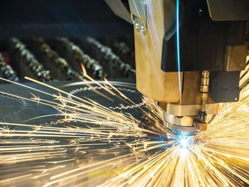
Kerf in laser cutting is the width of the slot the beam leaves behind — the material melted or vaporised and blown out of the cut by the assist gas. Because that material is gone, the laser kerf decides where the finished edge of a part actually sits.
The word comes from woodworking, where the kerf is the width of the cut left by a saw blade. In laser cutting there is no blade, but the idea is identical: the cut has a width, and that width comes out of your material.
Kerf in laser cutting matters for two reasons. First, if the machine followed the drawn line exactly, every outside dimension would come out half a kerf too small on each side, and every hole half a kerf too large. Second, the kerf is not perfectly constant: it changes with thickness, focus, speed and gas, so any variation moves the finished edge.
For most parts the machine takes care of the first problem automatically, through kerf compensation. The second problem is the one that shows up in tight fits, and it is why measuring the laser kerf on your own material is worth doing.
Typical Laser Kerf Width by Laser Type and Thickness
On sheet metal, a fiber laser kerf is typically about 0.1 to 0.4 mm wide, widening toward 1 mm on thick plate; CO₂ lasers cutting wood and plastics typically leave about 0.25 to 0.5 mm. Published figures from laser job shops give the ranges below.
| Process and material | Typical kerf width | Source |
|---|---|---|
| Fiber laser, sheet metal (by alloy and thickness) | 0.127–0.381 mm (0.005–0.015 in) | Fabworks |
| Fiber laser, metal up to thick plate | 0.152–1 mm (0.006–0.040 in) | SendCutSend |
| CO₂ laser, wood and plastics | 0.254–0.508 mm (0.010–0.020 in) | SendCutSend |
| CNC router | Equal to the cutter diameter; smallest common bits about 3 mm (0.125 in) | SendCutSend |
The width depends mostly on thickness. On thin stainless or aluminium — the work the X6040 and X5 on our sheet metal laser cutting machine page are built for — the kerf sits at the narrow end of the range; on thick carbon steel cut with oxygen it moves toward the wide end, because the cut runs slower and the oxygen reaction burns a wider channel.
The kerf also tapers. Fabworks puts typical taper at about 0.025 mm for every 2.54 mm of thickness, so the laser kerf at the bottom of a thick plate is not the same as at the top. That is negligible on 1 mm sheet and worth allowing for on 20 mm plate.
Compared with other processes, the laser kerf is narrow. A router can never cut a gap narrower than its bit, which is why fine detail in metal goes to a laser, as we compare in our guide to router, fiber laser and knife cutting.
What Makes the Laser Kerf Wider or Narrower?
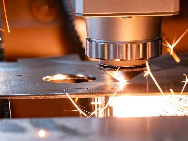
Material thickness, focus position, laser power and speed, assist gas and nozzle size all change the kerf in laser cutting — and anything that puts more heat into the cut widens it.
Thickness. Thicker material needs slower speeds and a longer path through the beam’s focus, so the kerf gets wider and tapers more. It is the single biggest factor.
Focus position and spot size. The beam is narrowest at its focus. Moving the focus into the material for a thick nitrogen cut, or above it for an oxygen cut, changes the width at the top and bottom of the kerf.
Power and speed. More energy per millimetre of cut — higher power or lower speed — melts more material and widens the kerf. Cutting too slowly on thin sheet is a common reason for kerfs that measure wider than expected.
Assist gas. Oxygen on carbon steel adds heat through its reaction with the iron and tends to produce a wider kerf than nitrogen. How each gas changes the cut is set out in our fiber laser cutting thickness chart.
Nozzle condition. A worn or damaged nozzle disturbs the gas jet, which roughens the cut face and can widen the kerf unevenly. It is one of the cheapest things to check when kerf starts to drift.
Kerf Compensation: How the Machine Offsets the Cut Path
Kerf compensation shifts the laser’s path sideways by half the kerf width, outward on outside profiles and inward on holes, so the finished part matches the drawing. It is set in the CAM software or the machine controller, not in your drawing.
Without compensation, the beam centre would follow the drawn line and remove half a kerf on each side of it. A 100 mm square would come out about one kerf width smaller, and a 10 mm hole about one kerf width larger.
With compensation, the controller offsets the path so the edge of the kerf, not its centre, sits on the line. The operator enters the measured kerf for that material and thickness, and the machine applies it to every contour.
That is why most laser shops ask for a DXF or DWG drawn at nominal size. If you shrink holes or enlarge outlines yourself to allow for kerf, and the shop also applies compensation, the part is corrected twice and comes out wrong.
To measure the laser kerf on your own material, cut a test square without compensation and measure it. The kerf is the drawn size minus the measured size. A row of strips cut side by side and measured together gives a more accurate average, because it spreads measuring error across several cuts. Kerf variation is one of several error sources we cover in our guide to laser cutting tolerances.
Designing Around Kerf: Tab-and-Slot, Press Fits and Fine Detail
Design fits and fine features around the kerf by drawing at nominal size, letting the shop compensate, and allowing a clearance that suits how the parts go together. Most kerf problems appear where two laser-cut parts have to meet.
Tab-and-slot joints. A slot and tab drawn at exactly the same size will not assemble if the kerf varies slightly the wrong way. Add a small clearance to the slot for a slip fit, or leave it at nominal for a tight fit that you test first. The same joints used on tube frames are covered in our tube laser cutting design tips.
Press fits. A laser-cut hole is not a reamed hole. Where a pin or bearing needs an interference fit, cut the hole slightly undersize and finish it, rather than relying on the kerf to land within a few hundredths.
Minimum feature width. A web or strip narrower than a few kerf widths overheats as the beam passes on both sides. Fine lettering and thin bridges in decorative panels are where this shows first.
Nesting and common-line cutting. Parts nested together need a gap of at least one kerf between them. Common-line cutting uses a single cut as the edge of two parts, which saves material and time, but only works when both parts can accept the same kerf position.
For thin, detailed parts where kerf and small features matter most, a high-dynamics machine such as the MNT X6040 holds the path steadier through tight corners than a heavier machine built for plate.
Frequently Asked Questions
What is kerf on a laser?
Kerf is the width of material a laser removes as it cuts — the slot left behind once the melted or vaporised metal has been blown out. On a fiber laser cutting sheet metal it is typically about 0.1 to 0.4 mm wide, and the machine offsets its path by half the kerf so parts come out at drawn size.
What is the typical kerf width range for laser cutting?
Laser job shops publish about 0.127–0.381 mm for fiber lasers on sheet metal, up to about 1 mm on thick plate, and about 0.254–0.508 mm for CO₂ lasers on wood and plastics. Thickness, focus, power, speed and assist gas move the kerf within those ranges.
How do you figure out the kerf of a laser?
Cut a test square of known size without kerf compensation and measure it: the kerf is the drawn size minus the measured size. Cutting several strips side by side and measuring them together gives a more accurate average for that material and thickness.
What is a standard kerf?
There is no single standard kerf, because it depends on the process, material and thickness. As a working figure, a fiber laser on thin sheet metal sits at the narrow end of the published 0.127–0.381 mm range and widens with thickness; a CNC router’s kerf equals its bit diameter, often 3 mm or more.
Should I adjust my drawing for laser kerf?
Usually not. Draw parts at nominal size and let the laser shop apply kerf compensation in the controller or CAM software. If you also adjust the drawing, the part is corrected twice. Only design in clearance where parts fit together, such as tab-and-slot joints.
How deep should a kerf cut be?
In laser cutting the kerf runs through the full thickness of the material, because the part is cut free. Partial-depth kerfs belong to scoring and kerf bending in wood; in sheet metal, a controlled bend line is usually made with a pattern of through-cuts or a press brake instead.
Kerf in laser cutting is easiest to settle on your own material. Send us a drawing with the material and thickness, and we will cut a free sample and tell you the kerf we used, so your fits are designed on real numbers. Contact our engineering team to arrange it, or compare the machines on our sheet metal laser cutting machine page.