Flatbed cutter print-to-cut drift is the gap between the printed artwork and the knife path. Its shape often points to the cause.
A constant offset points to a different cause than drift that grows toward the far edge. Calibrating before checking the file, marks and material can hide the symptom and worsen the next job.
Use the checks below to isolate the error on printed packaging board or other sheet material. The same logic applies to print finishing, but mark patterns and calibration steps depend on your RIP, camera and cutter model.
What Flatbed Cutter Print-to-Cut Registration Can Correct
Registration lets a flatbed cutter locate the printed sheet and align the cut path to marks generated with the print job. Depending on the camera and controller, the machine may compensate for position, rotation, scale, or combinations of these. It cannot correct every form of material distortion.
The print file contains artwork and cut contours. A RIP or design workflow adds marks that the cutter’s camera can detect and relate to the cut data. The print and cut files must come from the same approved job version and use the same page size and orientation.
Registration can correct only the shifts and distortions supported by its mark pattern and software model. A simple mark layout may handle a shift or rotation. Some systems can use additional or distributed marks to handle longer jobs or local variation. Check the cutter and RIP documentation before changing mark count, spacing or shape; unsupported marks can create a new detection problem.
Registration also has limits. A camera may align a sheet while the board bows, slips or stretches between printing and cutting. A single global correction cannot make every point match if the sheet changes non-uniformly. On packaging, this can move a logo toward a cut edge or leave a fold line off the printed panel.
For a flatbed cutter used for print finishing, first decide whether the error comes from the file, printed sheet, loading, mark reading or machine setup. That diagnosis determines whether to re-export, reload, adjust the media process or run the manufacturer’s calibration routine.
Read the Cut Pattern Before Changing Settings
Compare the error at the near edge, center and far edge before touching calibration. A consistent offset, a growing error and a local mismatch point to different causes, so record the pattern on the sheet rather than making a blind correction.
Use this table as a first-pass diagnosis. It is a troubleshooting guide, not a substitute for the procedures for your specific cutter.
| What you see | Likely causes to check | First check |
|---|---|---|
| Every cut is shifted in roughly the same direction and distance | Origin, sheet loading reference, camera-to-tool offset or calibration | Confirm the sheet orientation and origin, then run the cutter’s approved calibration check |
| Error grows from the near edge toward the far edge | Print scaling, mismatched print/cut versions, media feed or dimensional change | Compare known mark distances in the artwork and on the printed sheet |
| One side aligns while the opposite side is rotated or skewed | Sheet loaded out of square, feed skew, or a mark pattern that cannot describe the rotation | Square the sheet to the machine reference and inspect every expected mark |
| Some areas align, but one area is locally off | Board warp, local stretch, lamination tension, or a print defect | Check the sheet flatness and compare marks around the affected area |
| The camera fails to find marks or finds them intermittently | Low contrast, marks clipped or covered, surface glare, incorrect mark type or RIP setup | Inspect the printed marks under the cutter’s normal lighting and confirm the selected mark preset |
Look at the direction as well as the size. If all four corners move together, check origin or offset. If error grows toward the far edge, check scale and feed. If the sides disagree, check sheet skew or local distortion.
Also separate “mark not found” from “mark found but cut is misplaced.” Detection failures point first to contrast, print quality, mark layout or camera setup. A repeatable offset after successful detection points more toward the file relationship, origin or calibration.
As one manufacturer-specific example, Graphtec’s print-and-cut troubleshooting guide separates mark-reading, scale and offset symptoms for its cutter families. Use the pattern-based checks as a reference and follow the instructions for your own cutter and controller.

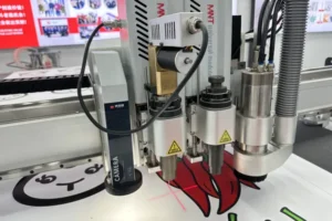
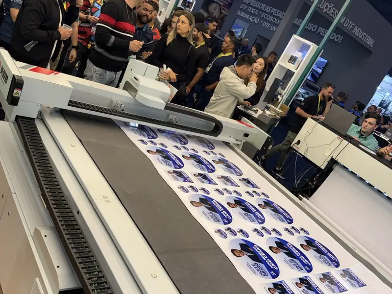
Live MNT CR 2516T label-cutting demo at Future Print 2026; this image shows the workflow, not a measured registration-error result.
Check the File, Marks and Sheet in This Order
Check the job file and media before changing the cutter’s calibration. A repeatable print-to-cut test is only useful when the print and cut data describe the same artwork at the same scale.
- Confirm the job revision. Export artwork and cut contours from the same approved file. If either changed, regenerate both. Confirm page size, orientation, origin and contour settings.
- Check print scaling. In the print dialog, verify that the job is output at its intended size. Check the RIP and printer driver too; scaling can be set in more than one place. Then compare a known distance on the printed sheet with the source file before changing cutter calibration.
- Check that the marks match the cutter preset. Use the mark type, size, spacing and margins supported by the RIP and cutter. Marks should be fully printed, high contrast and clear of artwork, trim, seams or other obstructions. Do not resize them independently in one file.
- Confirm the RIP workflow. Check that the selected cutter, mark preset and contour settings are compatible and belong to the same job. Some RIPs disable conflicting print-and-cut options; consult that RIP’s documentation if a setting is unavailable.
- Check sheet orientation and loading. Load the printed side in the expected direction, square the sheet against the machine’s reference, and make sure it stays flat under vacuum or hold-down. For roll or conveyor work, check that the media tracks consistently through the feed.
- Check the surface and material condition. Glossy or reflective surfaces can make camera reading harder on some systems. Temperature and relative humidity also affect paper and board properties; ASTM’s conditioning practice highlights these effects. Keep the print and cut test under the same material and shop conditions as the production job.
Change one variable at a time and save the original settings. If correcting print scale fixes far-edge drift, update the print preset. If squaring the sheet fixes diagonal error, correct the loading reference instead of adding a digital offset to every job.
This sequence is especially useful when a shop changes between corrugated board, folding carton and foam board. MNT’s cardboard cutting machine guide covers the cut-and-crease side of packaging work; the packaging sampling guide covers the sample workflow. Registration troubleshooting begins with the printed sheet and file relationship.
Run a Controlled Print-to-Cut Test on Your Packaging Stock
Use a test sheet with marks near the corners and checks through the center, then compare the cut at the near, middle and far edges. This shows whether the error is uniform, progressive or local without relying on a complex customer design.
Use the actual board grade, print workflow, lamination state and sheet size you intend to run. Put simple cut paths beside the marks and through the center. Include long horizontal and vertical references to expose scale or skew. Use the registration pattern supported by your controller; distributed or segmented marks are appropriate only when the machine and RIP support them.
Print and cut without changing scale, orientation, tension or camera settings between steps. Measure or photograph the result at the near edge, center and far edge. Record whether the camera found every mark, which edges align, and whether the offset changes direction or size. Repeat the same test once to see whether the result is stable.
A simple scale check can help: compare a known distance between printed marks with the same distance in the source file. For example, if an 800 mm reference in the file measures 800.8 mm on the print, the print is 0.1% larger on that axis. That is an illustrative calculation, not a machine specification. Verify measurements with a suitable scale and use the cutter’s approved correction process.
Keep the result with the material preset: stock and thickness, print/RIP settings, mark pattern, cutter model, loading direction and measured error. This gives the next operator a baseline. A sample on the customer’s own material can also validate a C2516T configuration before purchase.
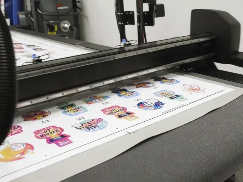
A printed label sheet on the MNT CR 2516T during a live demo. Use the controlled test above to measure alignment on your own stock.
When the Problem Is Outside the Cutter
If the error follows one print file, printer, laminate or material batch, investigate that part of the workflow before recalibrating the cutter. A cutter can detect and align to marks, but it cannot restore a printed sheet that has changed shape after the marks were created.
Compare a known-good file with the problem job. If it cuts correctly on the same stock and setup, inspect the problem file’s revision, scale, page size and RIP preset. If both drift, inspect loading, feed and machine alignment. If drift appears after lamination, repeat the test afterward and review tension and handling.
Paper and paperboard are affected by their conditioning environment, so changes in temperature and relative humidity can alter the material’s physical behavior. ASTM’s conditioning practice for paper and paper products describes the effect of temperature and relative humidity on physical properties. For repeatable packaging work, store and test stock under conditions close to production rather than assuming every nominally identical sheet will behave the same way.
Calibrate when a controlled test shows a consistent machine-level error after the file, marks and loading are checked. Follow the maker’s procedure and save the original values first. Do not change camera offsets to compensate for a scaled file or inconsistent loading.
If you cannot isolate the cause, send the machine supplier the printed test sheet, original print file, cut file, material and thickness, print/RIP settings, sheet size, and photos of the near, center and far-edge results. For MNT, that information lets the engineering team reproduce the issue on a sample instead of guessing from a single finished carton. The broader digital cutting table buying guide explains what to confirm about camera registration, feed method and tool configuration before ordering.
Flatbed Cutter Print-to-Cut Registration FAQs
Why does the cut drift farther off near the end of a printed sheet?
A growing error often points to print scaling, media feed, sheet skew or dimensional change. Compare mark spacing at both ends and confirm the files use the same scale before calibration.
What does a constant cut offset across the whole sheet mean?
A uniform shift can come from the job origin, loading reference or camera-to-tool calibration. Confirm sheet orientation and matching print/cut files, then follow the cutter’s calibration procedure if the offset remains.
How many registration marks should a packaging job use?
Use the pattern supported by the RIP and cutter. Longer jobs may need distributed marks if the system supports them; marks outside the approved preset can prevent detection.
Can a camera correct a warped or stretched board?
Not always. Registration corrects only the changes supported by the camera and controller. Local warping may remain between marks, so test the board flat and after lamination or finishing.
Should I recalibrate the cutter for every new material?
No. Keep machine calibration stable and test the material with the correct hold-down, feed and marks. Recalibrate only when a controlled check shows a repeatable machine-level error.
What should I send a supplier to diagnose print-to-cut drift?
Send the print and cut files, material and thickness, sheet size, RIP settings, mark pattern, loading direction, and near/center/far-edge photos. Say whether the camera found every mark and whether the error was constant or growing.
When packaging contours drift, the error pattern is the first clue. Check the same-version files, print scale, mark layout, sheet loading and material condition before changing the cutter’s calibration. If the issue remains, a controlled test on the actual packaging stock gives the supplier enough evidence to recommend the next adjustment.
For an MNT sample test, send the printed sheet, cut file, board grade, thickness, sheet size and the result you need through MNT’s engineering contact page. Review the flatbed cutter and C2516T pages for registration and feeding options.